
A utility-scale solar farm is, fundamentally, a large DC generating system connected to an AC grid; and the job of electrical design is to define every element of that connection.
For example, a 100 MW solar farm requires:
- Site Layouts
- Technology Choices
- Layout Optimisation
- Electrical System Design
- Grid Interconnection
Each of these involves hundreds of detailed design decisions that flow through to the electrical drawing package. At the IFC stage, deliverables include all comments and revisions, as well as equipment data sheets that are sure to be used for construction.
Every cable size in the field, every relay parameter, every earthing point traces back to a specific drawing in the electrical design package.
This guide explains what a complete solar farm electrical design package contains, what each deliverable must include, and how the drawings interconnect across disciplines.
The Foundation: The AC Single-Line Diagram
The single-line diagram is an essential component of the electrical drawing set for a utility-scale solar power plant. It is a simplified schematic that illustrates the overall electrical system from the panels all the way out to the point of interconnection.
The AC SLD is the master electrical drawing, which all other electrical deliverables reference and must be consistent with. It’s the common reference that ensures each construction subcontractor understands how its work integrates with the whole.
The SLD shows the major components of the solar power plant, and how they are interconnected, as well as the direction of power flow.
For a utility-scale solar farm, the AC SLD must show:
- DC to AC Conversion Layer: Each inverter block is represented with its DC input configuration, its AC output voltage and current ratings, and its interconnection to the MV collection system.
- Medium-Voltage Collection System: The MV reticulation is shown with bus configurations, circuit breakers, current transformer (CT) and voltage transformer (VT) positions, and feeder groupings.
- Substation and Step-Up Transformer: The substation SLD shows the step-up transformer configuration (delta-wye or wye-wye, vector group, impedance), high-voltage switchgear, bus arrangement, and grid connection point.
- Protection Devices: Protection device selection must be consistent with the protection coordination study, and the SLD is the document that makes protection philosophy visible to every stakeholder, from the lender's technical advisor to the DNSP.
- Metering Arrangement: Revenue metering and check metering positions are specified on the SLD, with meter type and accuracy class. This must be consistent with AEMO's metering requirements for NEM registration.
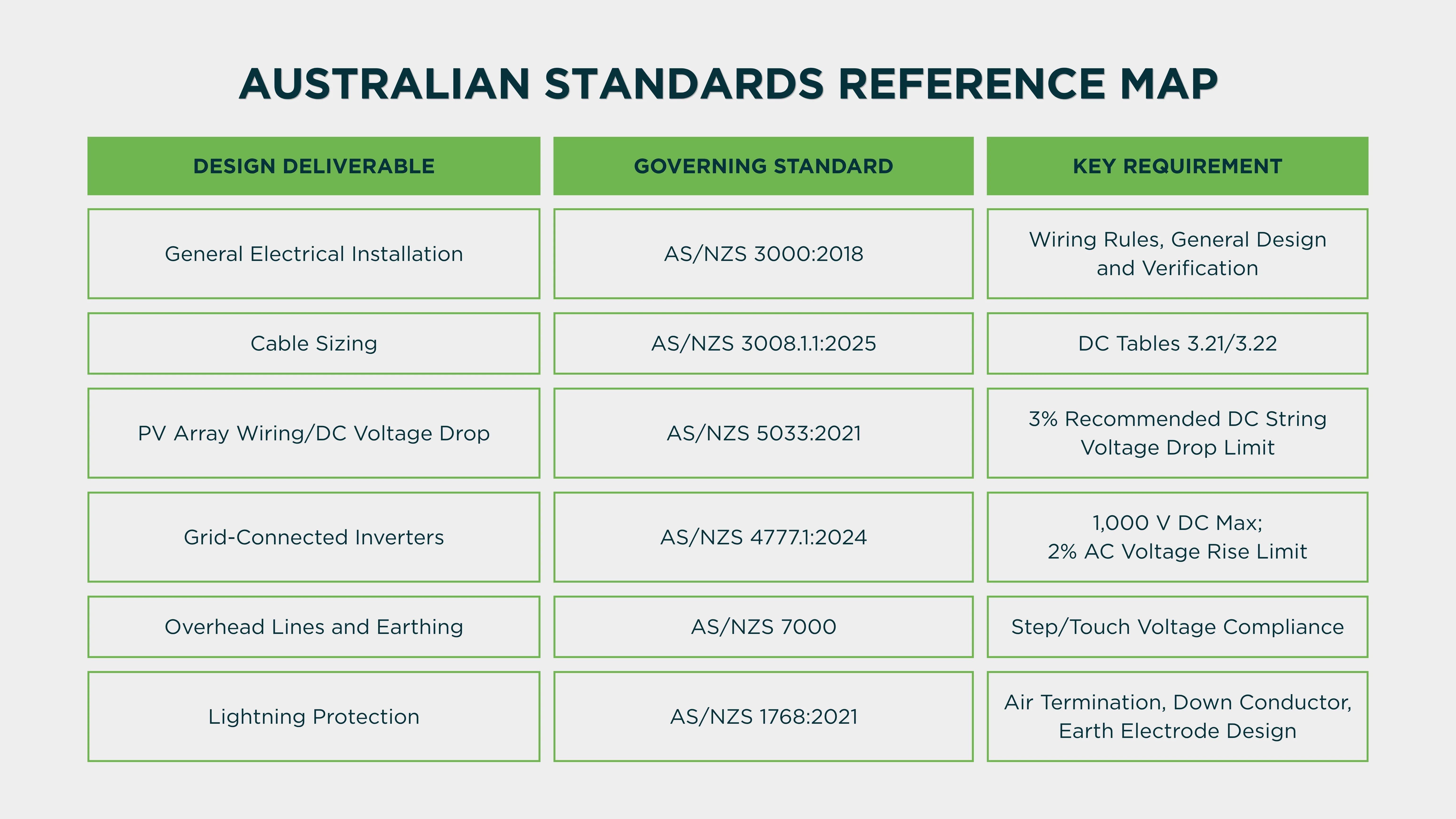
DC Electrical Design: String Configuration and DC Reticulation
The DC electrical design is where string sizing, DC/AC ratios typically between 1.2 and 1.35, and tracker or fixed-tilt selection combine into the DC electrical configuration.
String Voltage and Configuration
String configuration is one of the first electrical design decisions. The maximum string voltage must comply with both the inverter's maximum DC input voltage and the applicable Australian Standards. Under AS/NZS 4777.1:2024, the maximum permitted DC voltage for standard residential and commercial installations is 1,000 V DC.
The number of modules per string is calculated from the temperature-corrected Voc limit and Vmp operating range.
DC Reticulation Layout
The DC reticulation layout drawing shows:
- String groupings and string combiner box (SCB) locations on the site layout
- DC cable routing from module strings to SCBs to inverter DC inputs
- DC cable types, sizes, and voltage ratings for each section of the circuit
- Fuse or circuit breaker ratings at each SCB position
All DC cable sizing must comply with AS/NZS 3008.1.1:2025. From June 2026, DC cable sizing must use the new dedicated DC current rating tables (Tables 3.21 and 3.22), not the old AC-table-with-1.155-factor method. Voltage drop on DC string cables must not exceed 3% or 5% maximum per AS/NZS 5033.
Cable Schedule: The Master Electrical Register
The SLD provides architectural clarity. The cable schedule provides the operational detail, every conductor on the project listed with its unique identifier, specification, route, and compliance.
The IFC cable schedule for a solar farm lists every cable with:
- Cable Identification Number: A unique, structured identifier that traces every cable to its SLD circuit reference and physical location.
- From/To References: Exact terminal references at each end, consistent with the SLD and the wiring diagrams. A cable schedule with From/To references that don't match the SLD is a document control failure waiting to cause a commissioning problem.
- Cable Specification: Conductor material, insulation type, number of cores, conductor cross-section, voltage rating, and armouring.
- Cable Length: Estimated from the DC reticulation or MV cable route drawings, including 2 m per termination end and a minimum 10% procurement contingency.
- Voltage Drop: Calculated voltage drop percentage for the cable run, confirming compliance with the applicable standard.
- Short-Circuit Withstand Reference: The adiabatic calculation confirming the cable can survive the prospective fault current for the protective device clearing time.
Protection Relay Design and Settings
Protection relay design is the most technically critical element of solar farm electrical design, and the one with the most direct impact on AEMO GPS compliance.
AEMO GPS applications require power system modelling in PSS/E and PSCAD to demonstrate fault ride-through and frequency response. The protection relay settings must be consistent with the approved R1 model; relays that trip inside the ride-through boundary invalidate the GPS compliance evidence.
The protection design deliverables include:
- Protection Philosophy Document: A narrative and schematic document explaining the overall protection strategy; what protection is provided at each voltage level, how protection zones are defined, and how protection coordination is achieved.
- Protection Coordination Study: A time-current characteristic analysis confirming that protection devices operate in the correct sequence under fault conditions, which produces the relay settings and fuse ratings that are entered into documents.
- Protection Relay Settings Documents: One document per protection relay, specifying firmware version, relay type, and every protection element parameter. The relay settings must be formally reviewed and approved by the Owner's Engineer before IFC issue.
- Protection Settings Consistency with GPS R1 Model: For NEM-connected solar farms, the protection relay settings must be consistent with the GPS R1 power system model submitted to AEMO.
Earthing and Lighting Protection Design
Earthing design for a solar farm must satisfy two separate requirements:
- Step and Touch Voltage Limits: The earthing grid must limit step and touch voltage at any point on the site to the values specified in AS/NZS 7000 for the system fault current and fault clearing time. This requires a grid impedance study that confirms the earthing grid design achieves compliant touch and step voltage levels.
- Lightning Protection: The lightning protection system is designed to AS/NZS 1768:2021. For solar farms, the exposed tracker structures, combiner boxes, and substation buildings all require coordinated lightning protection.
The earthing and lightning protection layout drawing shows the earthing grid conductor routing, earthing electrode positions, equipotential bonding connections, and lightning air termination network, referenced to the earthing design calculation for compliance evidence.
SCADA and Communications Design
The SCADA design defines the information architecture of the solar farm; how operating data flows from inverters and sensors to the site control system, and from the site to AEMO's market management system and the asset owner's remote monitoring platform.
The SCADA electrical design deliverables include:
- SCADA Communications Architecture Drawing: Shows the network topology, typically a fibre optic ring connecting RTUs at each inverter block to the site SCADA server, with a separate communications path for AEMO MMS telemetry.
- RTU and SCADA Server Specifications: Hardware and software specifications for the remote terminal units, SCADA server, and human-machine interface, consistent with AEMO's current MMS interface requirements for NEM registration.
- Inverter Management Controller (IMC) Configuration: The plant-level controller setpoints that govern the reactive power dispatch, active power curtailment, and frequency response behaviour of the full inverter fleet.
- AEMO MMS Interface Specification: A document confirming that the SCADA configuration meets AEMO's specific telemetry requirements, a prerequisite for MMS registration and commencement of NEM market dispatch.
Partner with ElectraGlobe for Your Solar Farm Electrical Design
Every element of a utility-scale solar farm electrical design requires electrical engineering expertise specific to the Australian regulatory environment and the technical requirements.
ElectraGlobe is Australia's specialist renewable energy engineering consultancy. Our electrical design team delivers complete solar farm electrical packages coordinated across disciplines and consistent with the GPS R1 model from day one.
- AC SLD
- DC Reticulation
- MV Cable Routing
- IFC Cable Schedules
- Protection Philosophy
- Coordination Studies
Whether you are at concept design stage or moving into detailed engineering for an upcoming IFC package, our team delivers electrical designs that are compliant, coordinated, and construction-ready.
Discuss electrical design support with ElectraGlobe for your next solar farm project.
FAQ
What is a solar farm single-line diagram and what must it include?
The single-line diagram is a simplified schematic that illustrates the overall electrical system from the panels all the way out to the point of interconnection. For a utility-scale Australian solar farm, the SLD must include: every inverter block with its DC input configuration and AC output ratings; the MV collection system with bus arrangement, circuit breaker positions, and feeder groupings; the step-up transformer with vector group and impedance; the high-voltage substation with switchgear configuration and grid connection point; protection relay designations and function codes at every protection zone boundary; instrument transformer positions and ratios; and metering arrangement consistent with AEMO's NEM registration requirements.
What Australian standards govern solar farm electrical design?
Solar farm electrical design in Australia is governed by a suite of standards across different aspects of the electrical system:
- AS/NZS 3000:2018 governs the general requirements for electrical installation design and verification.
- AS/NZS 3008.1.1:2025 governs cable selection.
- AS/NZS 5033:2021 governs PV array wiring.
- AS/NZS 4777.1:2024 governs grid-connected inverter installations.
- AS/NZS 7000 governs overhead line and earthing design.
- AS/NZS 1768:2021 governs lightning protection.